The Drip Drop by Nebiyu Tadesse // Get Wet
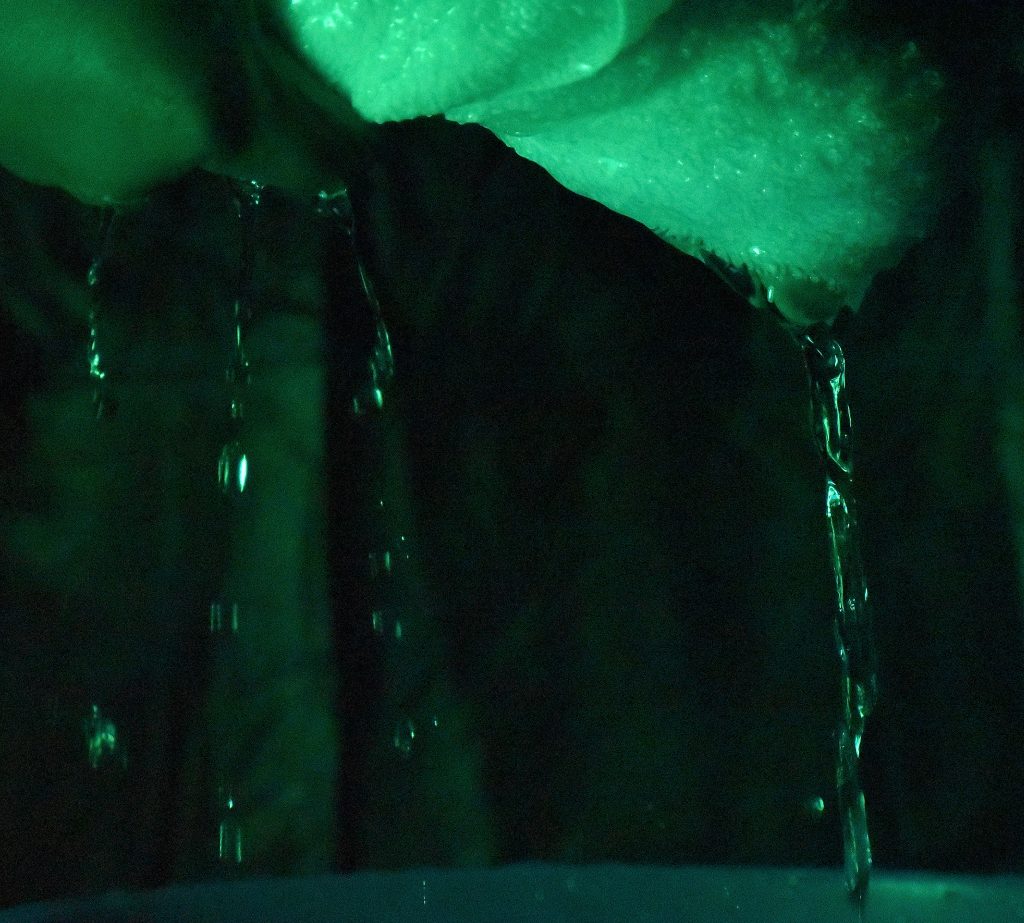
Water drops from a towel showing the fluid’s tendency to flow along a surface, showcasing surface tension, until it reaches a local minimum. It then breaks its surface tension due to the velocity it has, gravity, and the flow that’s pushing it from right behind.